Impellers & shafts
The impeller is where the process actually happens. Get the pumping pattern right and dissolution is uniform, the batch is repeatable and the drive stays cool. Get it wrong and you build a machine that stirs the top metre and leaves a bed of solids on the floor.
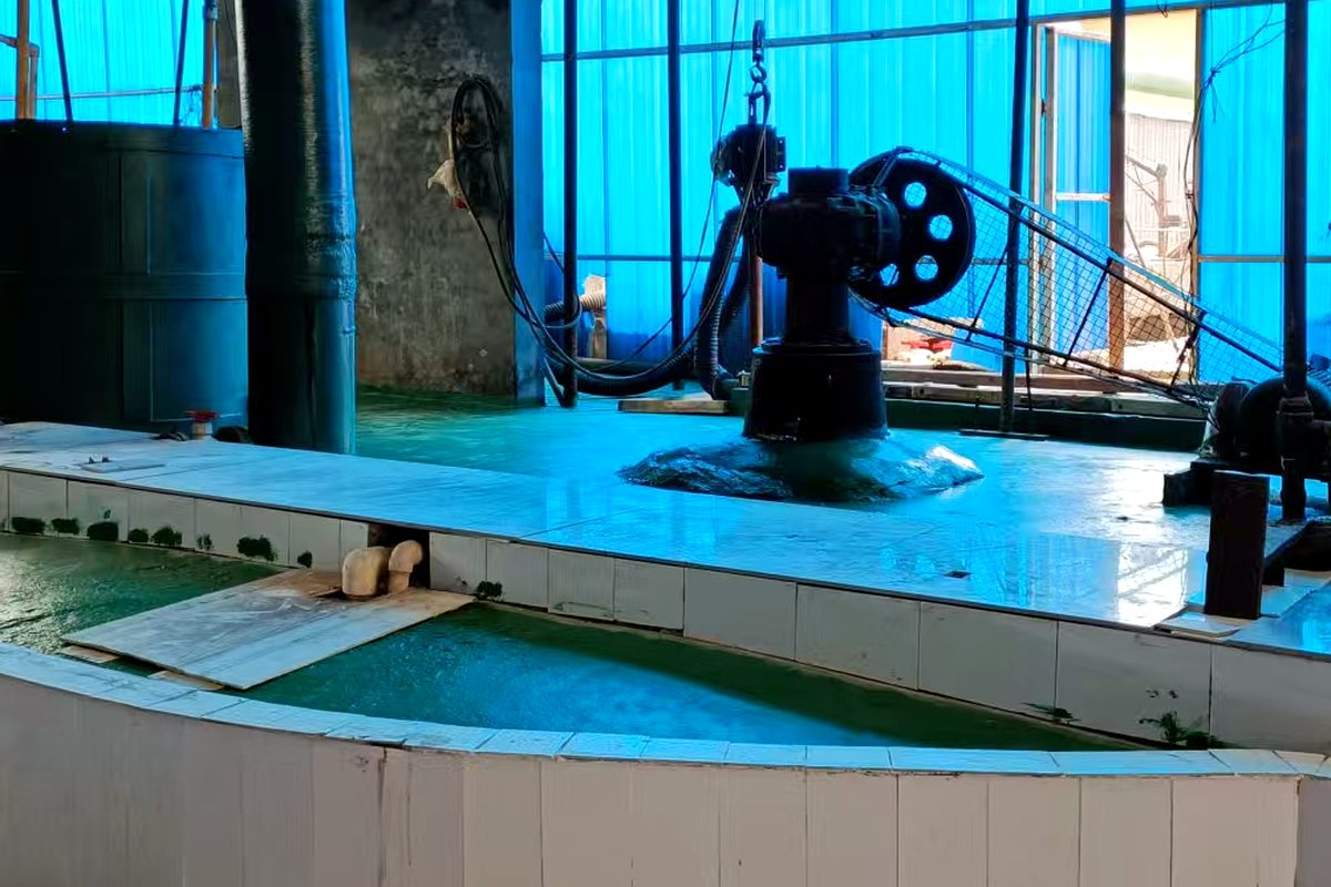
Two jobs, two patterns
Dissolution needs axial flow: a 45° pitched-blade or hydrofoil impeller pushes liquid down the centre and up the wall, sweeping the cone of solids at the bottom. Keeping a dense slurry in suspension needs radial flow: a flat-blade turbine throws material outward along the base.
For PAC duty we usually specify a two-impeller shaft — a pitched-blade unit low in the vessel for suspension and a second, smaller unit higher up to break the vortex and improve gas disengagement. It costs a little more than one big impeller and behaves far better at high solids.
Geometry that matters
- Impeller diameter 0.4–0.6 × vessel diameter; below 0.35 D the bottom sweep is too weak to resuspend settled solids
- Off-bottom clearance 0.15–0.25 × liquid height, measured to the impeller centreline
- Four blades at 45° as standard; six for higher shear at the same power
- Tip speed 2–5 m/s. Faster than that and you emulsify the acid mist instead of releasing it, which loads the scrubber
- Shaft in 316L clad or solid Hastelloy C when chloride levels are high; a rubber-covered shaft is cheaper but fails at the flange
- Steady bearing or a bottom steady bush on shafts longer than 3.5 m
Typical assemblies
| Vessel | Impeller | Diameter | Speed | Shaft |
|---|---|---|---|---|
| 10 m³ | 4 × 45° pitched blade | Φ900 | 80 rpm | Φ80 solid 316L clad |
| 20 m³ | 2-stage pitched blade | Φ1,100 | 70 rpm | Φ95 solid 316L clad |
| 30 m³ | 2-stage pitched blade | Φ1,250 | 60 rpm | Φ110 clad / Hastelloy |
| 50 m³ | 2-stage + steady bush | Φ1,500 | 55 rpm | Φ130 clad / Hastelloy |
Diameter and speed are paired to keep tip speed in the 2–5 m/s band. Larger impellers at lower speed give the same pumping with less shear.
How to tell it is wrong
- 01
Solids settle within minutes of stopping
Bottom sweep is too weak. Increase diameter before increasing speed — diameter raises flow at constant power more efficiently than rpm.
- 02
A vortex forms and the surface funnels
Too much axial energy for the vessel geometry. Add baffles, lower the impeller, or reduce speed and increase diameter.
- 03
Drive runs hot and trips on overload
Usually a settled bed at start-up, or an impeller buried in a heavy heel. Check start-up procedure before blaming the gearbox.
- 04
Product varies batch to batch
Poor top-to-bottom turnover. Add the upper impeller; a single low impeller mixes the bottom third and leaves the rest stratified.
Questions we are asked
Is a rubber-covered shaft acceptable?
On short shafts in mild duty, yes. On 3 m+ shafts the coating cracks at the flange and chloride gets underneath, which is worse than bare clad steel because you cannot see it. For PAC we default to 316L clad or Hastelloy.
Can we reuse impellers from an old line?
Often yes, if the diameter and pattern match the new duty and the metallurgy suits the liquor. Send us the drawing; we will check tip speed and shaft stress before reusing anything.
Do we need a variable speed drive?
It pays back where the batch has distinct phases — fast dispersion at the start, gentle turnover during polymerisation. Where the duty is constant, a fixed speed with correct impeller geometry is simpler and cheaper to maintain.